Geometry Definition
The definition of a simulation geometry includes the description of regions (range shifters, etc. ), fields, phantom and other physical parts of a simulation, that should be included in the particle tracking. All the elements of a simulation geometry are placed in Room region.
Region definition
Region is the fundamental building block for defining the geometry of a simulation. Currently, FRED is working only in Cartesian coordinate system and allows for regions with the shape of a rectangular box. A region is described by a set of parameters defining its field of reference (FoR), material, scoring and many others. Some of the parameters are mandatory, which is explicitly marked and the default parameters for the optional are given.
- IDregionID (mandatory)
Name or number identifying the region.
- O = [0, 0, 0]
Origin of the region, namely the coordinates in the Room frame of the pivot point.
- pivot = [0.5,0.5,0.5]
Origin of the region FoR in local normalized coordinates. By default, is the central point of the box.
- f = [0,0,1]
Region front vector in the Room reference frame, i.e. components of the e3 basis vector.
- u = [0,1,0]
Region up vector in the Room reference frame, i.e. components of the e2 basis vector.
- l = [1,0,0]
Region left vector in the Room reference frame, i.e. components of the e1 basis vector.
The front, up, and left vectors are normalized internally to unit vectors, so they can be more easily specified in input. For instance, f=[1,1,0] corresponds to a horizontal direction at 45° with respect to X and Y axes. Only two direction vectors can be specified, the third one is automatically determined by constructing a standard orthonormal basis. For instance, the left vector is determined using the cross product, i.e. l = u x f.
- L = [1,1,1]
Region extent, i.e. size of the region bounding box.
- voxels = [1,1,1]
Number of volume subdivisions along each direction.
- maxStepSize = 10
Maximum geometrical step length (in cm) allowed inside this region.
- rescale = 1
Rescaling factor for the whole region. It can be used for instance to shrink or inflate a voxel map loaded from file.
- material = vacuum
Definition of homogeneous region, meaning that the region will be filled with a single material.
- CTscan = filename
Load a 3D voxel map from a CT scan with values in HU. A calibration curved is used to convert from HU to material composition and density.
- score = None
List of scorers requested for the region. Allowed dense scorers are:
Edep - map of deposited energy per primary [MeV]
dose - map of deposited dose [Gy]
dose-to-water - map of dose converted into dose-to-water [Gy]
LETd - map of dose-averaged LET [\(\mathrm{\frac{MeV\,cm^2}{g}}\)]
spectra - map of spectra for each voxel - see spectra scorer for more details
None - no scorer activated
- scoreij = None
List of influence matrix scorers for the region. Any quantity shown above can be defined here to be scored as an influence matrix. See influence matrix description for more details about the output file format.
- scoringMask - None
A mask describing the voxels to score. The mask applies for all scorers defined in the score and scoreij lists. The image can be of any type but must have the same voxel grid as the region. The quantity will be only scored for voxels with values larger than 0.
- lWriteDensity = False
Save the density map of the region. It can be helpful when loading the region properties for a CT scan in HU to check HU to density conversion.
- lWriteImat = False
Save the imat map, i.e. the index of materials.
- lWriteLETd_parts = False
Save the LETd numerator and denominator maps. These can be used to add the dose-averaged LET maps from multiple simulations (for instance for simulations of a single patient plan where multiple fields ware simulated separately). Than the final LETd map can be obtained by summing separately the numerators and denominators from multiple simulations, and calculating the quotient.
- lWriteCTHU = True
Save the CTHU map. It works only when CTscan is given. This map is basically a copy of a CT map given in CTscan. The saved file is used by sceneViewerFRED.py script to map a CT on scene and by mhd_overlay.py script to create a background for dose distribution.
- lWriteRSP = False
Save the relative stopping power map. It works only when CTscan is given. Values are taken from the HU calibration curve supplied to FRED.
Example
region: phantom ; O = [ 0, 0, 0]; L=[10,10,10]; f = [ 0, 0, 1] ; u = [ 0, 1, 0] ; pivot = [ 0.5, 0.5, 0.5]
region: detector_1 ; O = [ 20, 0, 20] ; L=[10,10,5]; f = [ 1, 0, 1] ; u = [ 0, 1, 0] ; pivot = [ 0.5, 0.5, 0]
region: detector_2 ; O = [ 0, 0, 35 ] ; L=[10,10,5]; f = [ 0, 0, 1] ; u = [ 0, 1, 0] ; pivot = [ 0.5, 0.5, 0]
region: detector_3 ; O = [ -15, 0,15] ; L=[10,10,5]; f = [ -1, 0, 1] ; u = [ 0, 1, 0] ; pivot = [ 0.5, 0.5, 0]
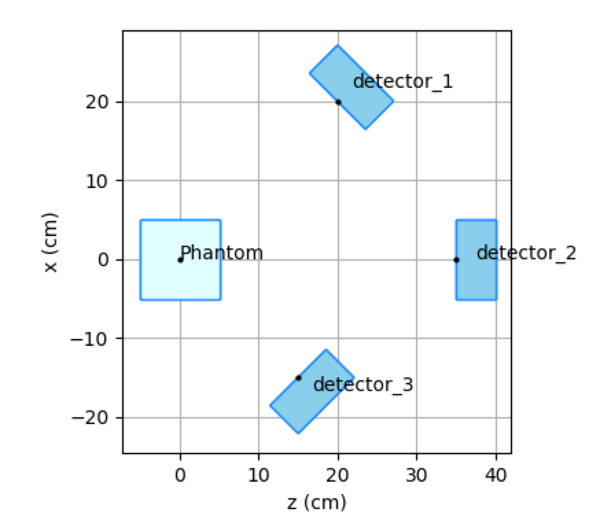
Phantom and 3 detectors pointing at the isocentre.
Field definition
Field is a structure describing an irradiation direction of a beam-like source of particles. It is essentially the definition of a reference frame with respect to the Room frame. The front vector is the main beam direction, also known as the beam-axis. The up and left vectors are defined as in the figure below.

Reference frame associated with a field.
A field is described with a few parameters. Some of the parameters are mandatory, which is explicitly marked and the default parameters for the optional are given.
- FID: fieldID (mandatory)
Number identifying the region.
- O = [0,0,0]
Origin of field in Room coordinates.
- f = [0,0,1]
Field front vector (i.e. direction of propagation) in the Room reference frame.
- u = [0,1,0]
Field up vector in the Room reference frame.
- exitWindowPlane = 0
Distance from the source to the exit window along the front direction. Particles are transported in vacuum up to the exit window, and in the Room material after exit.
The front and up vectors are normalized internally to unit vectors, so they can be more easily specified in input. For instance, f=[1,1,0] corresponds to a horizontal propagation direction at 45° with respect to X and Y axes.
If no fields are specified in the input file, then a field with ID=0 is created with parameters corresponding to the following line:
field: 0 ; O = [ 0, 0, -50]; f = [ 0, 0, 1] ; u = [ 0, 1, 0] ; L = [20,20,50] ; pivot = [0.5,0.5,0.2]
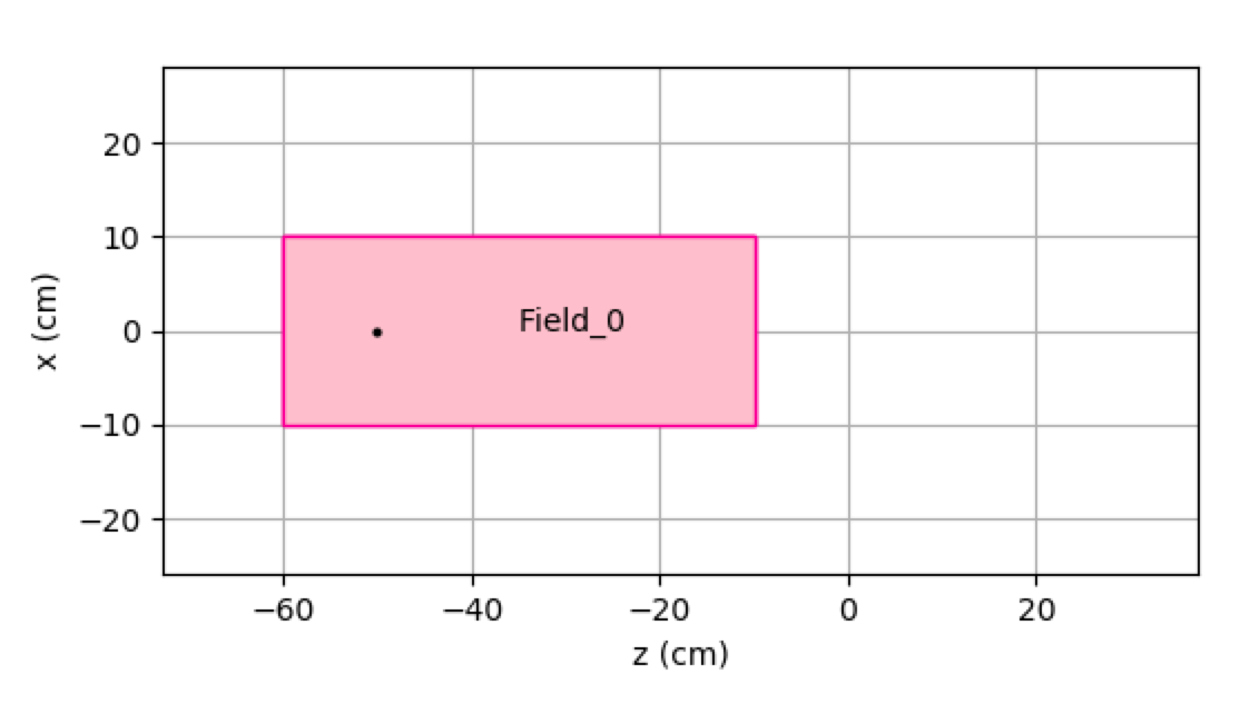
The default field Field_0.
Note
If you explicitly define one or more fields (for instance Field_1), then the default Field_0 is not created, and only the user defined fields are used.